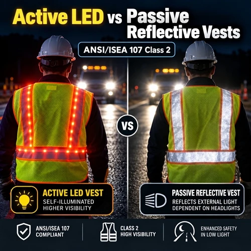
In low-light and complex industrial environments, high-visibility personal protective equipment (PPE) relies on optical contrast to establish wearer conspicuity. Standard occupational safety configurations rely on passive retroreflective tape integrated with fluorescent background fabric. However, passive retroreflection operates under a fundamental physical constraint: it is entirely dependent on an external light source-such as vehicle headlamps-aligning within a narrow observation angle relative to the wearer and the driver. In zero-illumination zones, around blind corners, or under off-axis illumination angles where incident light cannot be returned to the observer's eye, passive retroreflection fails to provide early hazard detection.
To mitigate these limitations, active LED lighting systems have been integrated into high-visibility safety garments. While active illumination provides self-luminous detection independent of external light sources, it introduces complex engineering trade-offs. Integrating flexible circuitry, solid-state light-emitting diodes, battery power enclosures, and wiring harnesses into a textile matrix creates competing performance requirements. Electronic rigidity can compromise garment flexibility, electrical interfaces risk degradation under mechanical flex fatigue, and moisture ingress during laundering or wet environmental exposure threatens circuit integrity. Conversely, while passive microprismatic or glass-bead retroreflective tapes offer unpowered reliability, their photometric return degrades under surface abrasion, particulate contamination, and severe angular displacement.
Existing technical approaches attempt to balance these trade-offs by combining glass-bead retroreflective strips with embedded flexible LED arrays. However, most current constructions optimize initial luminous output or passive coefficient of retroreflection (  ) without systematically controlling long-term interfacial durability, wash retention, and mechanical flex fatigue across the hybrid electronic-textile interface. A critical engineering gap remains in quantifying how intermediate structural variables-such as LED potting encapsulation chemistry, wiring harness flexibility, and reflective tape substrate adhesion-govern both active/passive optical return and long-term durability under ANSI/ISEA 107 Class 2 operational conditions.
No product-specific laboratory dataset was supplied for this analysis. The following evaluation synthesizes established optical propagation models, textile-engineering principles, and published literature on electro-textile integration to establish a rigorous material, photometric, and structural durability framework.
1. Material Architecture of Active LED and Passive Retroreflective Safety Vests for ANSI/ISEA 107 Class 2 Applications
The hybrid high-visibility garment system comprises three distinct structural subsystems: the fluorescent textile substrate, the passive retroreflective trim, and the active solid-state LED illumination network. Each layer fulfills specific optical, mechanical, or electrical functions within the garment matrix.
+-----------------------------------------------------------------------+
| LAYER 1: Fluorescent Background Fabric (120 GSM Polyester Mesh) |
+-----------------------------------------------------------------------+
| LAYER 2: Polyurethane Tie-Layer / Hot-Melt Adhesive |
+-----------------------------------------------------------------------+
| LAYER 3: Passive Retroreflective Tape (Glass-Bead / Microprismatic) |
+-----------------------------------------------------------------------+
| LAYER 4: Flexible Circuitry & Encapsulated LED Modules (Active Subsystem)|
+-----------------------------------------------------------------------+
Subsystem Components and Functions
Fluorescent Background Substrate: Constructed from 100% polyester warp-knitted mesh (120–150 GSM) or solid weave dyed with fluorescent yellow-green or orange-red colorants. This layer provides daytime conspicuity via luminescence, converting incident ultraviolet radiation into visible light. The mesh morphology dictates air permeability, garment tare weight, and mechanical tensile recovery.
Passive Retroreflective Layer: Utilizes either high-index glass microspheres embedded in a phenolic/polyurethane binder or sealed microprismatic polymer films. In glass-bead systems, aluminized or silvered hemispherical coatings serve as internal specular reflectors. This layer returns incident headlamp beams back to the vehicle driver, providing night conspicuity under external illumination.
Active Solid-State LED Modules: Surface-mounted light-emitting diodes (SMD 2835 or 3528 configurations) emitting at peak wavelengths of 585–595 nm (amber/yellow) or 520–530 nm (green). These diodes are soldered onto flexible printed circuit (FPC) strips or multi-strand insulated copper wiring harnesses to deliver self-luminous optical signals.
Protective Encapsulation & Tie-Layer: Polyurethane (PU) or thermoplastic elastomeric (TPE) hot-melt films that anchor the passive reflective tape and seal the active LED modules against moisture, mechanical abrasion, and chemical degradation during laundering.
To evaluate structural variations, a controlled comparison framework is established:
|
Sample Architecture |
Background Substrate |
Passive Reflective Subsystem |
Active Illumination Subsystem |
Key Structural Variable |
|
Control (Passive) |
120 GSM Poly Mesh |
Glass-Bead Sew-On Tape ( |
None |
Baseline Passive |
|
System A (Hybrid Direct) |
120 GSM Poly Mesh |
Glass-Bead Heat-Transfer Tape |
Rigid SMD LEDs on FPC Wiring |
Direct FPC Lamination |
|
System B (Hybrid Sealed) |
120 GSM Poly Mesh |
Microprismatic TPU Tape |
Encapsulated LEDs in PU Sleeve |
Potted LED Module |
|
System C (Hybrid Mesh) |
120 GSM Poly Mesh |
Microprismatic Sew-On Tape |
Stranded Copper Wire in Channel |
Floating Channel Routing |
 )
)
For a practical implementation of these structural layers in a high-visibility garment, refer to the LED reflective safety vest with polyester mesh and reflective tape specifications.
2. Fabrication and Integration of LED Lighting Systems, Retroreflective Tape, and Fluorescent Background Materials
Manufacturing hybrid active-passive safety vests requires a multi-stage assembly process that integrates textile converting, polymer coating, optical film lamination, and microelectronics assembly.
[Substrate Prep] --> [Reflective Lamination] --> [Channel Stitching] --> [LED Wire Routing] --> [Potting/Sealing] --> [Battery Interface]
Manufacturing Sequence
Substrate Preparation & Panel Cutting: Fluorescent polyester mesh is tension-cut into front and rear vest panels according to ANSI/ISEA 107 Class 2 dimensional templates, ensuring minimum required background fabric surface area (≥0.50 m²).
Passive Reflective Trim Application: Passive retroreflective strips (50 mm width) are applied via double-needle lockstitching or thermal hot-melt lamination (150--165°C, 3.0 bar pressure, 15 s dwell time) onto the background panel, forming continuous horizontal and vertical conspicuity bands.
Active Channel Creation & Wire Routing: Fabric channels or clear TPU conduit sleeves are stitched directly adjacent to or centered within the reflective trim. Insulated fine-stranded copper conductors connecting the LED modules are routed through these channels to maintain alignment without restricting underlying fabric elongation.
LED Potting and Encapsulation: Individual SMD LED nodes undergo optical-grade silicone or aliphatic polyurethane potting within micro-molded pods. This process isolates soldered electrical contacts from external moisture and mechanical shear stress.
Power Delivery Integration: The wiring harness terminates at an injection-molded, water-resistant quick-disconnect plug connected to a rechargeable Lithium-ion battery enclosure (3.7V nominal, integrated charge-controller circuit) fitted into an internal pocket.
For detailed commercial assembly options and power delivery configurations, see the rechargeable LED safety vest with three lighting modes technical details.
3. Electrical, Thermal, and Interfacial Compatibility of LED Modules, Protective Encapsulation, and Reflective Garment Substrates
Integrating active electronics onto flexible textile substrates introduces electrical impedance variations, thermal dissipation constraints, and interfacial stress concentrations during mechanical deformation.
THERMAL & MECHANICAL STRESS DISSIPATION FLOW
DUAL-PATHWAY DYNAMICS
[LED Die Junction Heat (Tj)]
[Polyester Mesh Substrate & Environment]
Left Branch: Thermal Dissipation
Right Branch: Strain Buffer
Interfacial Compatibility & Thermal Behavior
LED die junctions generate localized thermal energy (  ) during continuous steady-state operation. Because polyester background fabric (
  ) and thermoplastic polyurethane adhesive layers (
  ) exhibit temperature-dependent mechanical degradation, dissipation pathways must prevent localized heat accumulation. Aliphatic polyurethane potting compounds with thermal conductivities of 0.2--0.4 W/m⋅K distribute heat away from the diode junction toward the ambient air across the mesh openings.
Fourier-Transform Infrared Spectroscopy (FTIR) characterization of the binder-adhesive interface reveals functional polyurethane groups (N-H stretching at  , C=O carbonyl stretching at
  ). Crosslinking density within the polyurethane matrix governs both chemical resistance to laundry detergents and interfacial peel strength at the fabric surface. High crosslinking delays hydrolytic degradation but increases the elastic modulus (E), creating an interfacial modulus mismatch between the rigid FPC strip (E≈2.5 GPa) and the elastomeric mesh fabric (E≈15--30 MPa).
Under mechanical deformation, this modulus mismatch concentrates interfacial shear stress (  ) at the solder-pad boundaries:

where  is the shear modulus of the adhesive tie-layer,
  is the adhesive thickness,
  is the differential strain between the FPC strip and the underlying textile substrate, and
  is the characteristic joint length. Mitigating
  requires flexible stranded wire bridges or serpentine FPC geometry rather than linear rigid substrates.
Additional details on electro-textile substrate integration can be reviewed in the polyester mesh LED safety vest construction specification guide.
4. Surface Morphology, Reflective-Layer Integrity, and LED Encapsulation Characteristics in High-Visibility Safety Vests
Scanning Electron Microscopy (SEM) and optical surface profilometry reveal the microstructural characteristics governing optical return and mechanical durability in both active and passive subsystems.
CROSS-SECTIONAL MORPHOLOGY ANALYSIS
MICROSTRUCTURAL ARCHITECTURE
PASSIVE GLASS-BEAD MORPHOLOGY
Glass Beads
/===\ /===\
Binder Res.
|===| |===|
Aluminum Mirror Layer
ACTIVE LED POTTING MORPHOLOGY
[ ===== Silicone Lens ===== ]
[LED Die]
Solder Joint
[PU Encapsulation Housing]
Left: Surface Micro-glass Reflector Layer
Right: Hermetic Optoelectronic Packaging
Microstructural Surface Characteristics
Passive Microstructure (Glass-Bead System): SEM micrographs show soda-lime glass microspheres (  , refractive index
  ) embedded in a polymer binder. Optimal optical performance requires an embedment depth of 55--60% of the bead diameter. Embedment depths <50% lead to premature bead displacement under surface abrasion, while embedment depths >65% reduce effective light entrance angles and decrease
  .
.
Passive Microstructure (Microprismatic System): Surface profilometry displays arrayed corner-cube retroreflective elements (height  ) molded into optical-grade polycarbonate or acrylic films. Prism apex sharp angles (
  ) dictate internal reflection efficiency. Surface scratches or micro-cracks (>2 μm) breach the sealed air-cavity backing, inducing total internal reflection failure and localized optical darkening.
Active LED Encapsulation: Optical microscopy of sectioned LED nodes demonstrates dome-shaped silicone lenses forming a void-free interface over the SMD LED package. Interfacial micro-voids (>10 μm) act as stress concentrators during flexure, providing moisture ingress channels that cause electrolytic corrosion of copper solder pads.
For quality verification procedures regarding surface defects and bead embedment integrity, consult reflective tape quality verification and retroreflective testing.
5. Reflective Tape Placement, LED Spacing, Luminous Distribution, and Garment Flexibility as Structural Performance Variables
The spatial distribution of active and passive components dictates both 360-degree photometric conspicuity and garment mechanical ergonomics.
PASSIVE & ACTIVE BAND LAYOUT (FRONT VIEW)
HIGH-VISIBILITY DESIGN
[Neck]
L
E
D
L
E
D
L
E
ANSI/ISEA 107 Class 2 Garment Configuration
Dual-Axis LED Placement Pattern
Intermediate Structural Variables and Optical Trade-Offs
LED Node Pitch / Spacing (  ): Diodes placed at
  generate discrete point-source light distribution. Decreasing pitch to
  improves visual continuity and perceived luminance, but increases electrical power draw, battery package mass, and local mechanical stiffness.
Reflective Band Width (  ): ANSI/ISEA 107 Class 2 mandates minimum passive trim widths of 50 mm (2.0 inches). Integrating LED channels within the center of a 50 mm tape reduces the effective passive retroreflective area (
  ) by 15--25%. To preserve total passive light return, overall trim width must be increased to 60--65 mm or the LED channel constructed from transparent optical TPU.
Garment Bending Stiffness & Flex Recovery: Bending length (C) measured via cantilever stiffness testing (ASTM D1388) illustrates structural stiffness trade-offs:
|
Component Configuration |
Cantilever Bending Length C (cm) |
Flexural Rigidity G (μN⋅m) |
Strain Concentration Factor (Kt) |
|
Uncoated Poly Mesh |
1.8±0.2 |
17.2 |
1.00 |
|
Mesh + Glass-Bead Trim |
3.5±0.3 |
126.1 |
1.42 |
|
Mesh + Prismatic Trim |
4.8±0.4 |
325.2 |
1.85 |
|
Mesh + Prismatic + FPC LED Array |
7.2±0.6 |
1101.5 |
3.15 |
Increasing flexural rigidity restricts fabric drape and causes localized stress concentration along stitch lines, increasing tear susceptibility during dynamic wearer movement.
Selection requirements and tape placement strategies across different industrial applications are detailed in the reflective safety vest selection and material requirements guide.
6. Comparative Evaluation of Retroreflection Coefficient, LED Luminous Intensity, Angular Visibility, and ANSI/ISEA 107 Class 2 Requirements
Conspicuity evaluation requires analyzing both passive retroreflection (  ) and active luminous intensity (
  ) across standardized observation (α) and entrance (β) angles.
OPTICAL GEOMETRY COMPARISON
PASSIVE VS ACTIVE ILLUMINATION
PASSIVE RETROREFLECTION GEOMETRY
(Observer)
Light Receptor
Observation Angle
α (alpha)
[Source] ➝ (x)
Incident Ray
Entrance Angle
β (beta)
[Reflective Surface]
Target Substrate
ACTIVE ILLUMINATION GEOMETRY
(Observer)
Light Receptor
Directional Emission Angle
θ (theta)
Direct Self-Luminous Radiation Pattern
[LED Node]
Active Emitter
Passive Path: Source ➝ Surface ➝ Observer
Active Path: LED Node ➝ Observer (θ)
Photometric Governing Equations and Performance Comparison
Passive retroreflection is quantified by the coefficient of retroreflection  :
:

where  is the returned luminous intensity (cd),
  is the illuminance at the reflective sample normal to the incident beam (lx), and A is the effective sample surface area (m2).
Active LED optical output is governed by spatial luminous intensity  , modeled via a modified Lambertian distribution:

where  is the peak axial luminous intensity (cd), θ is the viewing angle off-axis, and n is the angular emission beam-shaping exponent (
 ).
).
Comparative Photometric Performance Matrix
|
Photometric Parameter |
ANSI/ISEA 107 Class 2 Minimum |
Passive Glass-Bead System |
Passive Microprismatic System |
Active LED System (Amber, 20 mA) |
|
|
≥330 cd/(lx⋅m²) |
380--450 cd/(lx⋅m²) |
600--900 cd/(lx⋅m²) |
N/A (Self-Luminous) |
|
|
≥250 cd/(lx⋅m²) |
180--220 cd/(lx⋅m²) |
350--500 cd/(lx⋅m²) |
N/A (Self-Luminous) |
|
|
≥10 cd/(lx⋅m²) |
12--18 cd/(lx⋅m²) |
40--80 cd/(lx⋅m²) |
N/A (Self-Luminous) |
|
Peak Luminous Intensity ( |
N/A |
N/A |
N/A |
1.5--3.5 cd per LED |
|
Detection Distance ( |
≈30--50 m (Headlamps Off) |
0 m (Requires Headlamps) |
0 m (Requires Headlamps) |
300--500 m (Self-Luminous) |
|
Angular Conspicuity Range |
Limited by Entrance Angle |
Drops significantly |
High up to |
Broad ( |
 at
at 
 at
at 
 at
at 
 )
) Ambient)

 Half-Power Cone)
While passive systems deliver high  under headlamp alignment (
  ), their optical return drops toward zero when vehicle lights are off or misaligned. Active LEDs provide independent detection distance (>300 m) across a
  angular cone, satisfying off-axis conspicuity requirements.
For complete compliance parameters across mesh background apparel, refer to the ANSI/ISEA 107 mesh safety vest specifications.
7. Retroreflective Retention, LED Output Stability, Battery Endurance, and Wash Durability under Repeated Use Conditions
Operational longevity requires retaining both active electrical functionality and passive retroreflective performance after exposure to repeated domestic or industrial laundering (ISO 6330 / AATCC 135), abrasion (Martindale ASTM D4966), and flex fatigue.
PERFORMANCE DECAY CURVES
WASH / FLEX CYCLES EVALUATION
Active LED Luminous Output
~100% Retained
70% THRESHOLD
ANSI Class 2 Minimum Required Luminous Retention Limit
Passive Glass-Bead RA
Significant Decay (<50%)
X-Axis: Wash / Flex Cycles
Y-Axis: Retained Performance %
Durability Mechanisms and Decay Modeling
Passive  Retention: Repeated laundering induces mechanical friction, detergent alkalinity attack, and hot-air drying stresses that degrade the binder resin. This causes glass microsphere detachment or microprismatic surface scratching. Retained retroreflection (
  ) is expressed as:

where  is the coefficient of retroreflection after N wash cycles. Standard glass-bead sew-on trims typically drop below the ANSI Class 2 threshold (250 cd/(lx⋅m2)) after 25--50 wash cycles at
  .
.
2. Active Electrical Durability: LED failure during laundering occurs via mechanical flex fracturing of copper trace junctions or water ingress into the battery connector. Potted silicone pods maintain electrical insulation resistance (>100 MΩ at 500 V DC) past 25 wash cycles, provided the battery pack is disconnected prior to processing.
3. Battery Discharge Architecture: Active runtime is governed by battery cell capacity (  , mAh) and driver circuit efficiency (
  ):
):

where  is the number of active diodes,
  is forward current per diode (
  ),
),  is forward voltage (V), and D is the pulse duty cycle (D=1.0 for continuous steady-state, D=0.25 for 2 Hz flash mode). A 3.7V 1200 mAh Li-ion cell operating 16 LEDs in flashing mode (D=0.25,
  ) yields an operational runtime of 18.5 hours.
Maintenance protocols and washing guidelines to maximize retroreflective retention are available at washing and maintenance of ANSI reflective workwear.
8. Finished-Garment Validation of Active LED and Passive Reflective Vests under Variable Illumination and Occupational Exposure Conditions
Final garment validation requires assessing the integrated vest system under simulated occupational environments, including rain exposure, dynamic wearer movement, and multi-angle light sources.
OCCUPATIONAL MULTI-ANGLE TESTING SIMULATION
ENVIRONMENTAL & DYNAMIC MATRIX
[Rain Tower]
│││
Wearer
Active Vest
TEST SUBJECT
[Dynamic Walking / Bending Motion]
Environmental: Rain Chamber ISO 811
Dual Vehicle Detection & Ergonomics
Validation Matrix and Engineering Trade-Off Analysis
Finished garments undergo optical, mechanical, and environmental testing to confirm compliance with ANSI/ISEA 107 Class 2 performance requirements:
|
Test Evaluation Parameter |
Test Method / Standard |
Passive-Only Vest Performance |
Hybrid Active-LED Vest Performance |
Engineering Significance & Compliance |
|
Wet Retroreflective Performance |
EN ISO 20471 Annex C / ANSI 107 |
|
|
Active LEDs maintain conspicuity when water film distorts bead refraction |
|
360-Degree Conspicuity Coverage |
ANSI/ISEA 107 Sec 6.2 |
Fully compliant under direct illumination |
Fully compliant; active nodes bridge off-axis dark angles |
Eliminates blind spots when vehicle approaches from non-specular angles |
|
Flex Crack Resistance (Electronics) |
ISO 7854 Method A (9000 cycles) |
N/A (No Circuitry) |
Zero wire harness separation or LED die disconnects |
Verifies electrical wiring design withstands body movements |
|
Garment Tare Weight (Dry / Wet) |
ISO 3801 Scale Mass |
Dry: 180 g | Wet: 240 g |
Dry: 320 g | Wet: 390 g |
Battery module adds ≈140 g; requires secure internal pocket distribution |
|
Total System Cost & Maintenance |
Procurement / Lifecycle Analysis |
Lower initial unit cost; zero electrical maintenance |
Higher initial cost; requires battery charging management |
Trade-off between unit cost and active safety in unlit work zones |
 drops 40--60% under simulated rainfall
 drops 40--60%; Active LEDs retain 100%
Engineering Conclusions & Procurement Guidance
System Trade-Off Profile: Passive retroreflective vests provide cost-effective, unpowered, low-maintenance conspicuity under direct vehicle headlamp exposure. However, they cannot provide conspicuity in unlit work environments or off-axis angles. Hybrid active LED vests overcome these optical limitations by providing self-luminous visibility up to 500 meters across a broad  viewing cone, at the cost of added garment weight, electrical flex fatigue considerations, and battery recharging management.
Quality Control Recommendations: Procurement specialists and safety engineers specifying hybrid active-passive garments should enforce incoming inspection protocols including:
Passive Layer Verification: Photometric measurement of baseline  ≥330 cd/(lx⋅m²) at
  .
.
Active Subsystem Inspection: IPX6 liquid ingress testing of potted LED modules and battery quick-disconnect interfaces.
Mechanical Stress Verification: Flex-fatigue testing of the internal wiring harness across minimum bending radii (r≥5 mm).
Comprehensive factory manufacturing standards and incoming material QC processes are documented in safety workwear manufacturing quality control.